Hi.
Camera matching in 3ds Max requires careful attention to detail and an understanding of perspective and camera principles. By accurately matching the virtual camera to the real-world camera, artists can create seamless compositions that blend real-world footage with 3D elements, enhancing the realism and immersion of their projects.
Here are some tips I’ve accumulated over the years, when matching the perspective of a photograph with a camera in 3ds Max, particularly when you don’t have a great deal of 3D information.
This is going to be a really long blog post though, as there is a lot to get through…
If you would prefer to have this emailed to you in PDF format, please feel free to enter your details below, and I’ll be happy to send it over –
Let me qualify the ‘great deal of 3d Information’ bit – we are not talking about what is known in the UK, as an ‘AVR’.
AVRs
Accurate Visual Representations (AVRs) or Verified View Montages (VVMs) have become common currency for large scale planning applications in the UK, particularly in London, where there are protected view corridors from key elevated positions at the periphery of the city, typically with their focus centred on the dome of St Pauls’ Cathedral.
There is a well documented methodology for the production of AVR images, which is often opened up for scrutiny and transparency. A quick web search for ‘Verified Views’ or ‘London View Management Framework’ will bring up lots of pdf reports detailing the process involved.
In a nutshell, they are reliant on having an accurate GPS enabled survey commissioned together with large format professional photography. The ground position of each photograph is surveyed and a notional lens height, typically 1.6m agreed. The coordinates for each camera position are recorded, alongside additional coordinates for key visible features appearing within each photograph. These ‘XYZ’ coordinates will be provided in a spreadsheet and this allows for the accurate positioning of a virtual camera by the 3D artist.
But I’m not referring to this well established process here. I’m talking about those occasions where yes, you have a siteplan, showing some neighbouring context, a photograph, and well, that’s it.
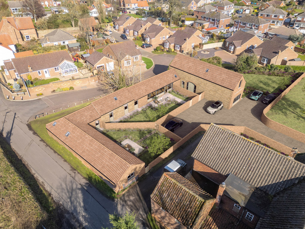
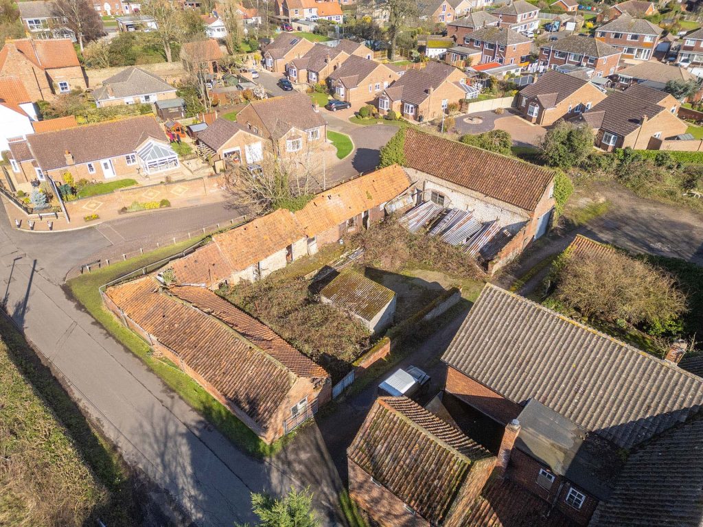
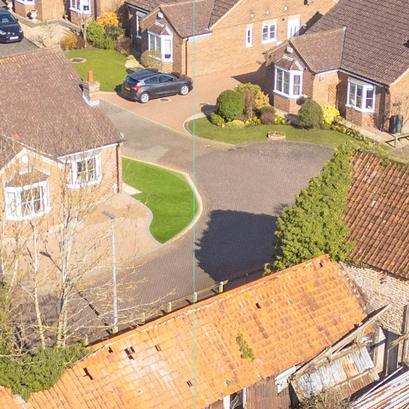
I’ll demonstrate my process via a recent barn conversion project. Here I was supplied with a drone photograph, shot by Will Selby
The scheme and corresponding siteplan were by supplied by Kelly MacPherson Architects
Where to start then?
I’ve chosen this project as it’s an elevated shot and so has an added complication with the camera floating off the ground somewhere.
I can see the shot was taken from a position around the bottom left corner of the siteplan, but first I’ll need to remove any lens distortion, and for that I’ll import it into Adobe Lightroom.
Most camera lenses will have some lens distortion, but our virtual camera in 3ds Max won’t, so it is a good idea to remove this, as it will lead to a better camera match. As we have the original, our shot has the metadata embedded within it and Lightroom (in this case I’m using the fuller Lightroom Classic software version) will detect and work with this.
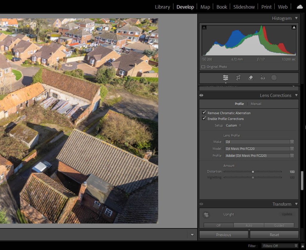
From the image’s metadata, Lightroom was able to establish the profile of the real-world camera, in this case a Majic Pro, and removed the lens distortion from around the edges. If the metadata isn’t there, then you would have to ‘switch to manual’ and either try and remove it by playing with the distortion slider in Lightroom, or finding out from the photographer what lens and camera model were used to create the shot, and seeing if there is a Lightroom lens preset to match. Failing that, it is a step that can be skipped, accepting that when you come to aligning your virtual camera, it will be less accurate at the outer edges of the shot.
Once you’ve removed the lens distortion (or not, if indeed that piece of the puzzle is missing!), then it’s time to export your backdrop (I always put them in a sub-folder imaginatively labelled ‘corrected’) and open up the exported copy into Photoshop. It’s also time to fire up 3ds Max too.
Finding the camera target position in Photoshop
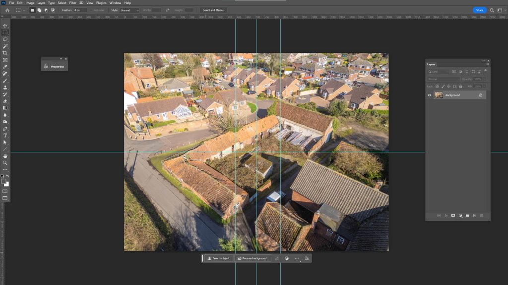
There are a couple of things we can establish from Photoshop, with the help of ‘guides. The first thing we can establish is where our camera target should be, and that’s the centre of the photograph.
Pressing Ctrl-R within Photoshop will bring up the rulers at the top and left edge, if they’re not already present. If you zoom completely out with Ctrl-0 and then click and drag from the left ruler, say, you will create a guide and it will ‘snap’ to the centre of the photo when you slide it towards the image centre, same process from the top ruler to get the horizontal centre.
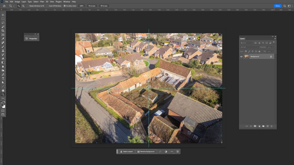
This is where your 3ds Max camera’s target should be positioned in 3D, within your model.
In this particular case, it’s on a patch of ground a few metres out from the existing middle facade.
Positioning the camera target as accurately as you can will pay dividends later on, so it’s worth persevering with this, in any way you can.
It’s also worth pointing out that the camera’s target point will only be in the centre of the image, if the original image is an uncropped original and wasn’t shot using a ‘shift-lens’.
Tilt-shift lenses are a specialist photography lens which allows you to move the glass optic of the lens without moving your camera, and are commonly used for high-end architectural photography. This is probably something to include in another post, but they allow buildings to be shot in ‘architectural’ 2-point perspective, with the walls of buildings remaining vertical and with the horizon line or ‘vanishing points’ offset from the horizontal centre of the image. Often the lens is ‘shifted’ up, to pull the horizon line down and reveal more sky in the shot.
Highly unlikely that our drone image was shot with a shift-lens though, so let’s move onto the next bit of detective work.
Setting things up in 3ds Max
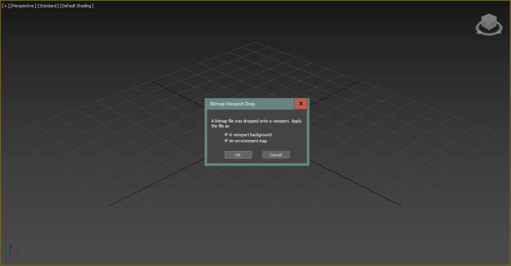
Before we carry on, we should import our backdrop photography into 3ds Max, and the easiest way to do this is to drag and drop it onto a 3ds Max viewport, preferably the default ‘perspective’ viewport, or if you’ve raced ahead and already created a camera, the corresponding camera viewport. This will bring up a dialogue box asking whether you want to set the image as both the viewport background and the environment map, and I usually do both.
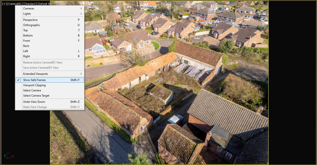
A few more things to do though. Firstly, make sure your render dimensions match those of the backdrop image, otherwise you will squash or stretch it in the viewport. Also, you’ll need to enable ‘Safe Frames’ to frame the backdrop correctly in the viewport, either by using the pulldown menu at the top right of the viewport, or typing Shift F.
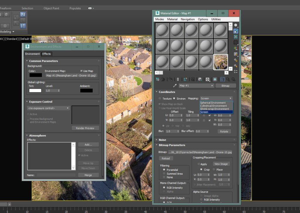
With the environment, you’ll need to drag and drop the environment map 3ds Max automatically created into an empty slot in your Material Editor and set its mapping to Screen, rather than Spherical Environment. This enables the background image to appear as it should if you decide to do a quick render.
What I plan to do is set up an initial camera and establish if I can align this to the backdrop using the methods outlined below. If I then accept that my camera’s alignment is close but not close enough, I’ll rely on this initial camera when working with 3ds Max’s inbuilt camera match utility.
Going back to Photoshop and looking at the central vertical guide, I can see it passes through certain key features on the ground, including of course, our target point.
Towards the top of the image I can see it clips a curved pavement, inset by maybe 40cm or so?
At the bottom, it more or less lines through with the edge of an existing building at ground level.
This is a lucky break for us in that, if I draw a line in 3ds Max, passing through these two points at ground level, our camera will be positioned (in X and Y at least) somewhere along this extended line
So far so good, although we’ve not thought about the camera’s Z position or angle or field of view. As our image was shot on a professional drone camera, then we can get a good approximation for our photograph’s field of view from its metadata, which we can access via ‘File Info’ in Photoshop.
Using the Image Metadata
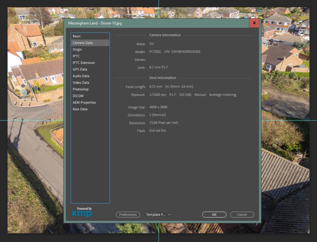
So this tells me that our 3ds Max camera lens should be in the region of a 24mm lens (on a 35mm equivalent, which is the 3ds Max default). I won’t get into the size differences of camera sensors within, for example, large format cameras or iPhones, the metadata will usually display a 35mm equivalent. I say in the region of a 24mm lens (or 73.74 degrees), as I find that with the original photographer focusing and zooming, this initial viewing angle should be treated as an approximation.
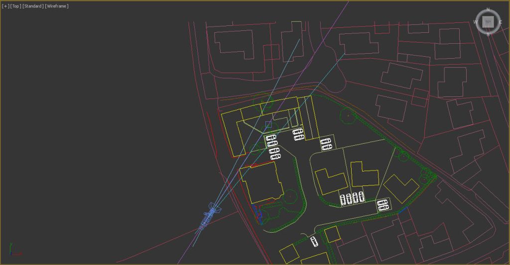
So our camera is positioned in plan, somewhere along this line, to the South West in this instance. How far along this line though?
I’ll add a few more vertical guides to Photoshop, either side of the image centre, and see what other existing features line through. I’ll then plot 2D lines between these features and see if they converge to a point, and give a further clue to where our camera should be in plan.
I should caveat this method of drawing lines in plan based upon existing features lining through in the background photography. It works really well when aligning to street or eye level photography, but I find less so with drone shots (my brain can’t fathom why exactly, maybe it’s something to do with the elevated 3 point perspective?) It does give a good starting point though, as will become more apparent further down.
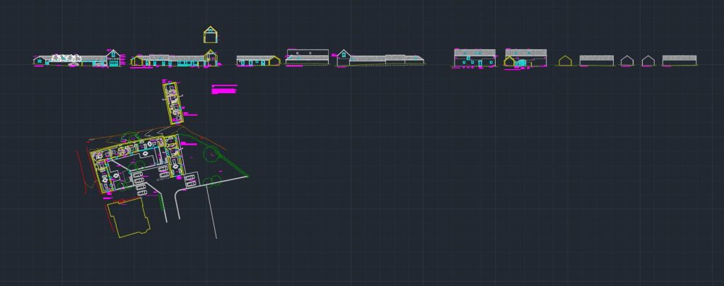
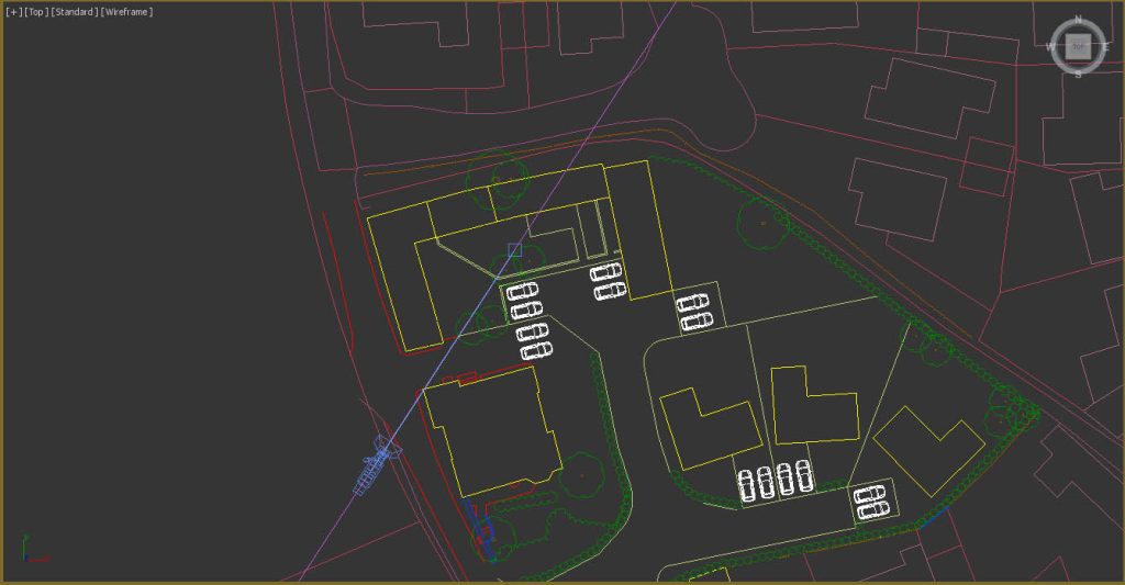
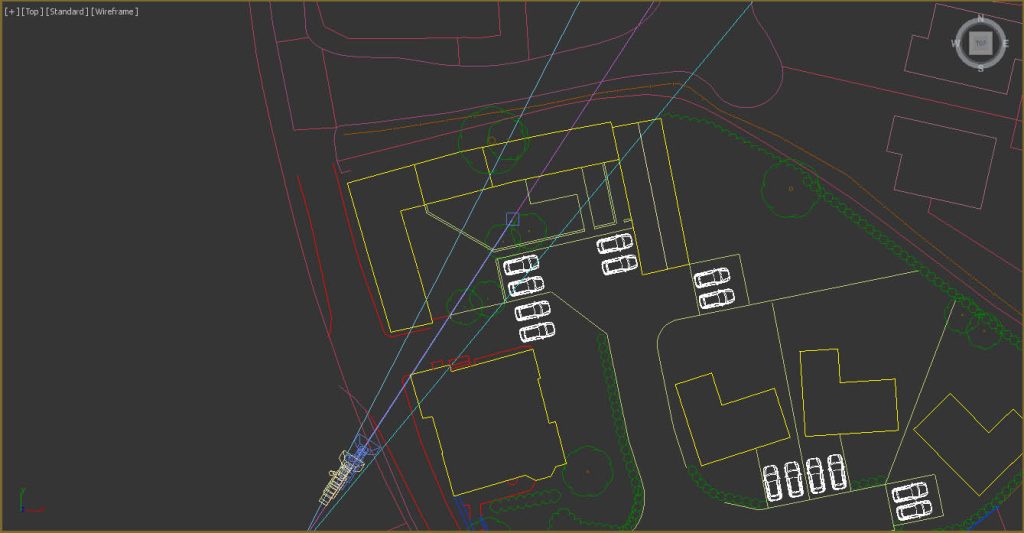
Here are my converging lines drawn in plan, in 3ds Max. I’ve positioned my camera over where they intersect.
So now it’s time to add, merge or Xref in the 3D model we intend to render and superimpose over our photograph. This will allow us to see how well we are doing with our camera alignment and help us establish how ‘high in the sky’ our camera position should be. I usually Xref in my proposed models, so I can select my camera easily without wading through a load of 3D objects.
As I mentioned early on, this particular project is a barn conversion, where the existing structure and roofs are to be refurbished, replenished and new openings made in the existing fabric. So the architects have already measured up the existing facades, and I was able to build an accurate model based on their drawings.
Not every project is the same of course, and you may find yourself building some of the existing neighbouring context yourself to help with camera alignments, or to cast proper shadows onto the proposed development when rendering.
There are various tips and tricks to help with this, which are again probably outside the scope of this blog post. You can open up Google Streetview and count bricks – 10 UK modern bricks including the mortar would be around 75cm in height, older ‘Imperial’ bricks are larger, around 83cm for 10 bricks and door heights in the UK are typically 210cm high and so forth.
I’ll guess an initial height or Z coordinate for our camera, of around 30 metres, and see what we get.
The initial camera alignment in 3ds Max
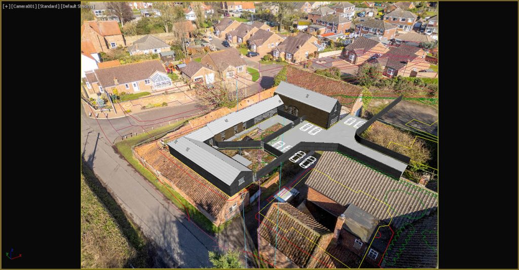
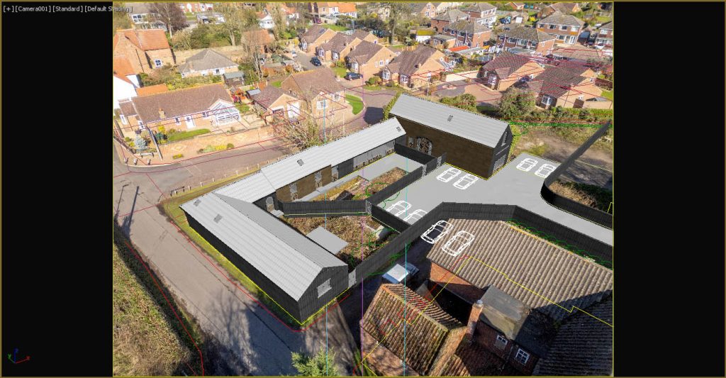
OK, so yes our model is too small compared to the existing structure in the photograph, but I’m encouraged by this, as the orientation looks good and so we are on the right track. I did tweak the camera’s Z coordinate further until I felt it looked about right.
We could either alter the camera’s field of view and zoom in, or move forwards. If I zoom in, then I think we diverge too far from one of our in theory ‘known known’s’, which would be the 24mm lens given by the photography’s metadata – zooming in gives a field of view angle of around 58 degrees, rather than the implied 73.74 degrees of a 24mm lens.
If I look at the original photograph more closely, I can see that its perspective is fairly extreme at the edges, suggesting a wide angle lens, which is what a 24mm lens is. So let me try moving forwards, or ‘dollying’ in along the camera’s local Z axis.
There is a dolly tool on the bottom right of the 3ds Max UI when looking at the camera viewport, but I prefer to use the ‘Transform Type-in’ dialog that comes with 3ds Max. Selecting our camera and pressing F12 will bring this dialog up, and allow us to alter our ‘Dolly’ factor. I’ll reduce it and move the camera closer-in, until the 3d model covers the corresponding buildings in the background photography.
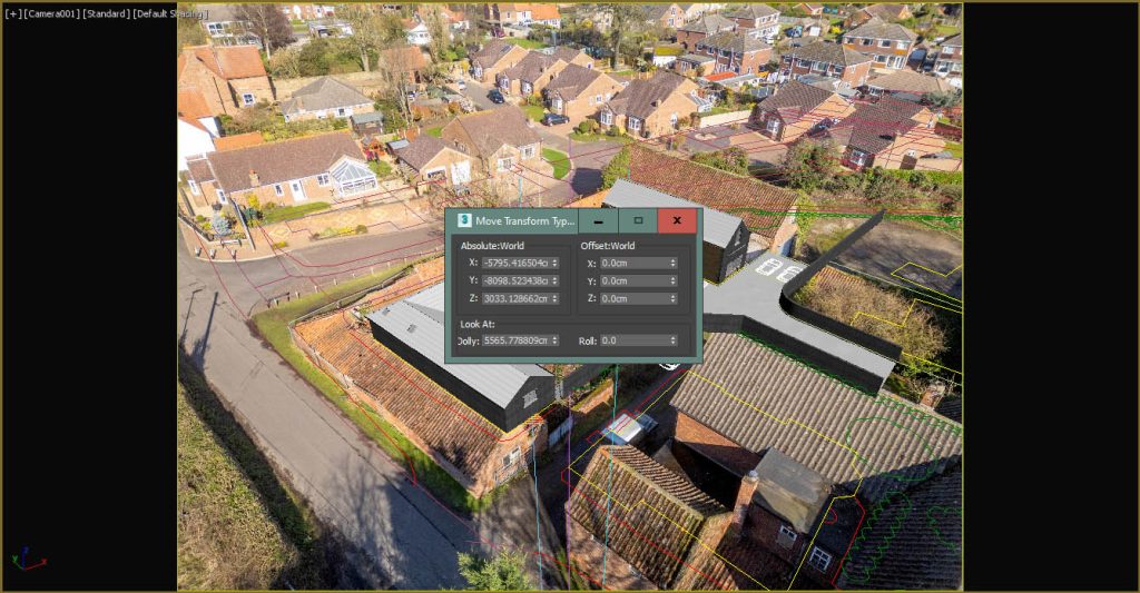
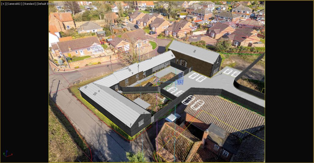
I think this is pretty good! My 3D model certainly looks like it belongs in the photograph.
I can see some divergence in this distance, around the roof on the larger two storey building.
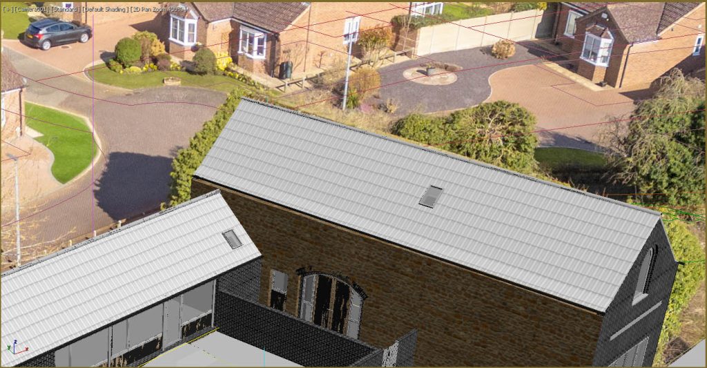
This could be for a few reasons, either our camera Z position is slightly out, or indeed the ridge line of the existing building isn’t level in actuality. Looking beyond our 3D model I can see that our 2D siteplan isn’t lining through either, but it would be wrong to assume that the existing ground plane is completely flat either whereas our imported siteplan is of course shown as 2D splines.
The camera match utility in 3ds Max
You could judge that our initial camera alignment is fine for marketing or ‘artist’s impression’ purposes.
If the image is meant for something more sensitive, like a planning application, then we should double check things, and the way I’m going to do that is by trying the 3ds Max camera match utility. I’ll do this to establish where 3ds Max ‘thinks’ the camera should be.
I don’t want to get into a detailed explanation of how to use the inbuilt camera matching utility in 3ds Max – I’m sure there are plenty of resources and youTube videos out there explaining the process.
It’s far easier setting it up from a camera position that is close to the desired output, and so we’ll use the camera we’ve manually positioned. Let’s call this camera camera001, and then the camera the utility will generate will be camera002.
The process is fairly straightforward. In the camera001 viewport you place 3d ‘camera match’ helpers in 3D space (by snapping to vertices on your 3D model), on obvious and visible existing features. You find the camera match helpers in the dropdown menu from the create > helpers panel. These could be corners of walls, roof apex points and you’ll need some on the ground and on either side of the vertical centre of the background image. I typically add around 8-12 or so.
Once you’ve got a good spread of 3D points, head over to the Utility panel and hunt for the camera match utility. It’s usually hidden by default.
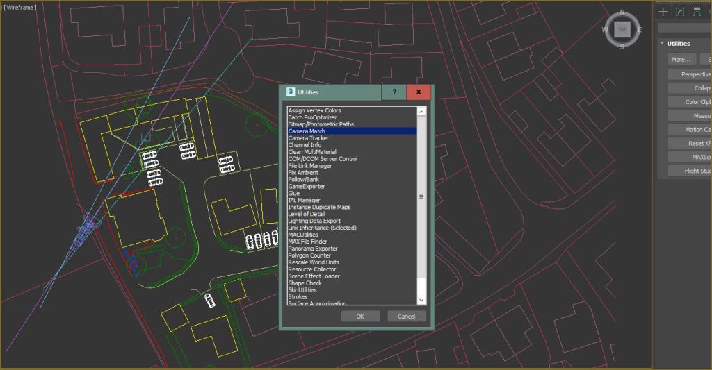
Next, you’ll need to hide your model (I also hid the siteplan) so you can see the background image underneath. Then it’s a case of assigning a corresponding 2D position or pixel on the image plane of the viewport background image that matches where you want the 3D equivalent camera match helper to align towards. Once you’ve done all this, head back to the camera match utility panel and click on ‘create camera’.
Unhide your geometry and siteplan, switch the viewport to the camera created by the utility (camera002 I’m guessing) and let’s see how it did.
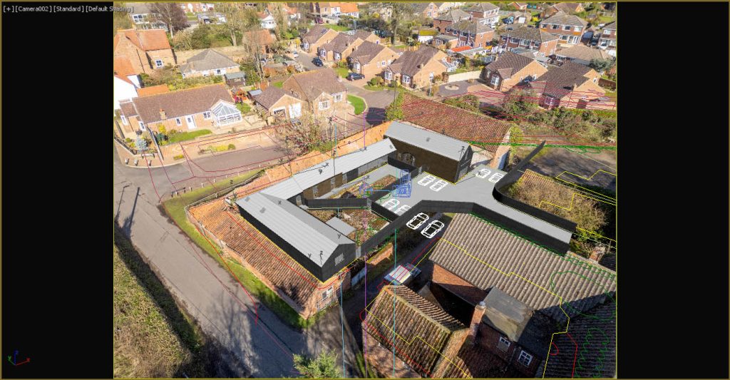
OK, it looks pretty good orientation wise, but the field of view isn’t correct – in my experience, the camera match utility is a bit hit and miss with the lens value, and if I select camera002 it tells me it has a viewing angle of 88 or so degrees rather than the 73.74 degrees of a 24mm lens. Let’s modify the camera created by the utility and tweak its field of view until it matches the scene better.
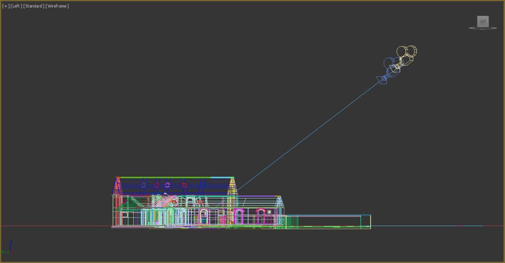
This is more like it. I can see we’re a bit further out than our manually positioned camera, and we have a slightly narrower field of view than a 24mm lens, of 69.6 degrees (remember that I mentioned the lens information in the photograph’s metadata should be taken as an initial guide only). The roof on the two storey barn looks better aligned too, as does our imported siteplan. I’ll switch to a plan view and look at the different positions of our two cameras. I’ll also do the same but looking from the left to see where we are in the Z axis.
Interesting that I wasn’t very far away with my initial camera.
What I tend to do now, is duplicate my initial camera and move it to the second camera’s position and match its field of view. The camera generated by the camera match utility is a ‘free’ camera and so doesn’t have a target object, and if I wanted to fine tune and tweak the alignment further, I find doing this is easier with a targeted camera.
A quick recap
I think that’s largely it. Here is a quick recap of the main process I use when aligning 3ds Max cameras to photography.
- Try and remove any lens distortion – I use Adobe Lightroom to help with this.
- See what can be gleaned from the photograph’s metadata, in particular the camera lens value.
- Establish the centrepoint of the photograph, and position your 3ds Max camera’s target point to the corresponding XYZ position in your 3D model.
- With the vertical centre of the photograph, find existing features top and bottom that fall along this centreline and plot an extended line between these features in your 3D model.
- Plot similar lines to the above, but using features either side of your vertical centreline, these lines should converge to a point in plan.
- Place your camera over this intersection point and adjust its height and field of view.
- If your manually placed camera’s alignment is ‘close but not close enough’ try working with the 3ds Max utility, assuming you have some contextual geometry which matches obvious features visible in your backdrop photography.
- Create a third camera and base it around both your initial camera, and the free camera created by the camera match facility, using your professional judgement on whether to tweak things further, or settle for an acceptable camera alignment.
One final point is that it’s always a good idea to keep a record of how you derived your camera position, particularly if it is to be submitted as a part of a planning application process.